
Contact points plate diagram
An extended overview can of course be found on wikipedia, however the principle of operation is simple. As the rotation of the crank shaft drives the cam shaft at a 2:1 rotation conversion for the little 4 stroke engine the asymmetrical end of the camshaft lobe presses against the spring arm of the breaker causing it to on the compression stroke 'contact' the grounding point. At a set point ideally just prior to Top Dead Centre the pressure from the cam on the breaker arm is released causing the points to separate and the resulting sudden change in current across the inductor of the ignition coil induces a voltage spike v(t) = L(di/dt). This spike is large enough to break down the dielectric strength of the gas-air gas mixture and the gases become ionized allowing electrons to travel across the spark plug gap igniting the fuel mixture at ~500-800C.
The procedure Honda prescribes for determining plate rotation requires that a) you have the engine mounted on the bike b) you have a 6v test bulb.
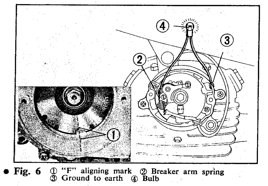
Honda's Recommended breaker alignment procedure
Unfortunately I have neither a, nor b so rather than hunt around for a multimeter it was far easier to modify the families emergency flashlight. Thankfully 4 years of labs left me with a wealth of spare wire and aligator grips, so in not time at all and using an excessive amount of packing tape I had come up with a rudimentary conductivity tester. Evidently the contact points are connected in the following picture as the bulb is illuminated.

Connection tester alligator clipped to breaker spring (red wire) and grounded to case (black)
To determine the separation point of the contacts the two adjustment screws on the contact plate must be loosened and the plate rotated such that the light on my conduction tester goes off when the F point on the crank shaft aligns with the index mark on the stator during the compression stroke. This is accomplished by rotating the crankshaft with a 14mm wrench until the F line and the index mark align, then using a flat head screw driver gently rotate the top plate CCW's until the bulb turns off. Once aligned tighten down the adjustment screws and check to see if the point is the same, I had to redo this a few times as the tightening causes the plate to shift. It was interesting to note that the pervious wear on the contact plate indicating where the plate had previously been tightened down was significantly off from the newly realized plate rotation. Perhaps this was the reason for wiper ring crack?

Crank plate (14mm bolt) with T (Top dead center) and F (Fire) marked
good points thanks
ReplyDeleteair jordan 11
ReplyDeletejordan 6
nfl jerseys cheap authentic free shipping
coach outlet online
hermes outlet
Michael Kors Bags
hermes belt
clarks shoes clearance
oakley
North Face Rain Jacket
oakley eyeglasses
michael kors handbag
nike outlet
coach shoes
fitflop shoes sale
michael kors outlet
coach outlet online
salomon boots
oakley
ray ban outlet store online
clarks shoes outlet
oakley.com
wholesale jordan shoes
cheap nfl jerseys
michael kors handbags clearance 75% off
red jordans
fitflops clearance
coach purses
North Face Jackets Clearance
jordans for women
coach wallets outlet
nike air max 90
guess
coach factory outlet online
North Face Sale
cheap nike air max
oakley sunglasses
cheap michael kors handbags
mbt shoes
20160316yxj